|
Article
Triple Stern Cannon Test Circuit
by
Chris Pearce
This little circuit allows you to test and tweak a set of triple stern
cannons individually, and fire them simultaneously on the water. It's a
fairly simple little circuit that bends the mind a bit, but gets the job
done.
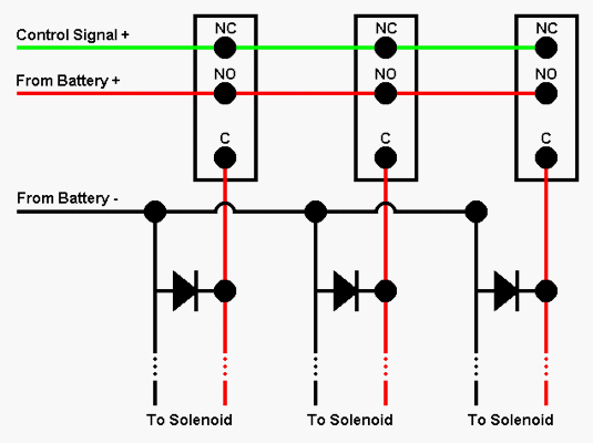
 |  | | The diagram for the cannon test circuit. |
Before getting into how to build one, let's discuss the basic concept
first. The concept of this circuit is based around the interesting uses of
the SPDT (single pole, double throw) switch. This switch allows you to
take a "common" (C) output and switch either of two inputs to that common
output. One input is the "normally closed" (NC) input. When the switch is
not pressed, the NC input is always routed to the C output. Conversely,
the "normally open" (NO) input remains open until the switch is pressed.
(Just like a normal SPST switch...)
That said, let's look at this circuit as though it were a single cannon
test switch. The first thing you'll notice is that the - (black) input
goes directly to the solenoid. This is the common ground. Second, you'll
notice that the common output from the switch goes to the other lead of
the solenoid. Now, if we just consider the "NC" portion of the switch,
you'll notice it's attached to the green, switched input from the radio
box. As a result, when the switch is not being pressed, the normal radio
controlled signal can pass through the switch to the solenoid and fire the
cannon. So, basically, until you press the switch, it acts as though it's
not even there. Now, the magic part of this arrangement is the red wire,
which goes to the normally open part of the switch. When the switch is
pressed, it disconnects from the NC (radio) input, and switches to the NO
(positive) input, bypassing the radio box, and sending a direct voltage to
fire the solenoid. And (of course) when you let go, the switch is
released, and returns to the NC (radio) input. Great, isn't it??? Best of
all, you'll notice that this circuit will work just as well with one
switch for one cannon, or two switches, for two cannons, three, or even
four switches for four cannons.
That said, there's one little detail to explain. The funny triangle
thing below the switch is called a diode. A diode is basically a one way
valve for electricity. It lets it flow one way, but not the other. The
reason there are diodes in this circuit is because of one of the funny
properties of solenoids. A solenoid is basically an electromagnet, and the
funny thing about electromagnets is that they use electricity to generate
magnetism. Well, that's not the really funny thing. The really funny thing
about them is that when you turn them off, the magnetism takes a very
brief instant to go away. During that brief instant, the coil of the
electromagnet generates a backwards electrical charge. If this backwards
voltage spike is not dealt with, it can eventually damage your switches,
or even your radio, and can definitely cause radio interference. Enter the
diode. If you buy some diodes (I use the 50V, 3A variety), you'll notice
that they have a black (or silver, or other contrasting color) band on one
end. This corresponds to the crossbar on the triangular "diode" symbol,
and indicates the direction that current is allowed to flow. As a result,
if you look at the diagram, the diodes are placed so that when the + side
is +, and the - side is - (as it should be), the diode is inactive and
preventing current flow. On the other hand, when the solenoid generates
one of those nasty reverse voltage spikes, the diode allows the current to
harmlessly pass through it, saving your switches (and radio) from damage
and interference.
To build this circuit, you merely have to pick up some diodes and SPDT
switches from Radio Shack, if you want to, or you can order fancier stuff
from your favorite electronics supplier. For those of you who want to get
fancy, the switch I like to use is C and K #8121SHZGE, available from Allied Electronics, and their stock
# is 676-0400, at a cost of about $5 each. Also, if you really need
details for the diodes, I like the 1N4004 type, which you can get from
Allied, #568-0144. Or, you can deal with the tedious catalog search tool
for your favorite electronics dealer.
Anyway, once you have all those fiddly parts, solder it all together
like in the diagram above. You might just want to test it with a
multimeter and clip leads before doing anything dangerous. Then, once you
have it all put together, connect your solenoids, and away you go. Hope it
works as good for you as it has for me!
Copyright © 2001 Chris Pearce
|

